By Rod Bland • Difficulty: Moderate
Learn how to upgrade or replace the memory in your 2018 Mac mini with this RAM replacement guide. The mini can support up to 64 GB of RAM, using any combination of 8 GB, 16 GB, or 32 GB DDR4-2666 SODIMM RAM modules.

- Use an opening tool to pry the bottom cover up off of the Mac mini.

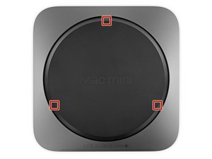
- Lift and remove the bottom cover.
- Align it carefully so that the words "Mac mini" can be read when the ports are facing you.
- Then, press down on the cover to snap its three hidden clips into place.

- Remove six TR6 Torx security screws securing the antenna plate, of the following lengths:
- Three 4.1 mm shoulder screws
- Three 1.8 mm screws


- With the Mac mini's ports facing you, carefully lift the antenna plate and slide it about an inch to the right.


- Use a T6 Torx driver to remove the 2.8 mm screw securing the antenna cable to the Mac mini's logic board.


- Use the point of a spudger or fine tweezers to gently pry the antenna cable connector straight up off its socket on the logic board.

- Remove the antenna plate from the Mac mini.


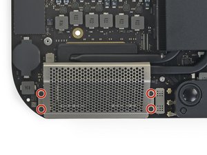
- Use a T6 Torx driver to remove the four 7.2 mm screws securing the fan:
- Two screws securing the fan to the logic board
- Two screws with rubber shoulders securing the fan to the exhaust vent


- Lift the fan from the flat edge where it meets the exhaust vent, being careful not to strain the fan cable underneath.


- Grasp the fan cable by all six wires and gently lift to unplug it from the logic board.

- Remove the fan.

- Grasp the power supply cable and lift to disconnect it from the logic board, wiggling as needed to loosen it up.


- Carefully lift the connector for the LED indicator light straight up to disconnect it from its socket on the logic board.


- Use a T10 Torx driver to remove the two 7.5 mm screws securing the logic board.


- Place a thumb at each end of the exhaust vent, over the fan screw holes.
- Push firmly in the direction of the ports until the logic board unclips and begins to slide out of the Mac mini.


- Slide the logic board out of the case.
- Use a T5 Torx driver to remove the four 2.8 mm screws securing the RAM shield.

- Lift the RAM shield and slide it off of the RAM assembly.


- Two clips secure each RAM module in place, one on each side. Using your fingers, spread the clips away from the RAM module.
- Optionally, you can slide the rubber covers off the metal clips—make you slide them back on after installing the RAM module.
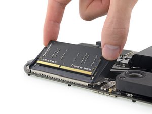
- Slide each RAM module straight out to remove it.


- Make sure the module is oriented correctly and the notch on the bottom is aligned, and then slide it in at about the same angle as you took it out. Press evenly until the gold contacts are no longer visible.
- Repeat for the second module.


- If the rubber guards interfere with the clips, spread the rubber guards away from the RAM with one hand and use the other to angle the RAM modules into place. Then, release the guards.
To reassemble your device, follow the above steps in reverse order.
Take your e-waste to an R2 or e-Stewards certified recycler.
Repair didn’t go as planned? Check out our Answers community for troubleshooting help.