By Craig Lloyd • Difficulty: Moderate
Follow this guide to replace a faulty or damaged LCD on the Nintendo Switch Lite.
The Switch Lite uses JIS screws, but you can use a Phillips screwdriver in a pinch. Be very careful not to strip the screws. iFixit's Phillips bits are designed to be cross-compatible with JIS-style screws.
Note: This guide is for the LCD only. If you're replacing the screen (the LCD attached to the digitizer) follow this guide. If the display glass is cracked or shattered, but the LCD still works, you’ll need to replace the digitizer instead.
Note: Removing the joysticks and buttons isn’t required, but it makes this repair much easier.
Note: This procedure requires removing the shield plate and heat sink. The thermal paste will need to be cleaned off of both components—as well as the CPU—and reapplied before reinstalling the shield plate and heat sink.

- Use a Y00 screwdriver to remove the four 6.3 mm-long screws securing the back panel.


- Use a JIS 000 driver or an official iFixit PH 000 driver to remove the following screws securing the back panel:
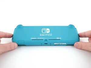
- Two 3.6 mm-long screws on the top of the device
- Two 3.6 mm-long screws on the bottom of the device


- Insert an opening tool into the left speaker grille on the bottom of the device.
- Twist the opening tool to release the clips securing the back panel.
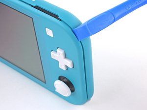

- Slide the opening tool around the bottom-left corner to release the clips on the left side of the device.


- Insert an opening tool into the right speaker grille on the bottom of the device.
- Twist the opening tool to release the clips.


- Slide and pry the opening tool around the bottom-right corner to release the clips on the right side of the device.


- Continue sliding and prying the opening tool along the gap on the top of the device to release the clips.


- Lift the bottom edge of the back panel, opening it like a book.
- Remove the back panel.

- Use a JIS 000 driver or an official iFixit PH 000 driver to remove the following four screws:
- Three 3.1 mm screws
- One 4.5 mm screw


- Use a spudger or your fingers to lift the shield plate up and out of the device.
- Remove the shield plate.


- Use an opening tool or your fingernail to flip up the small, hinged locking flap on the motherboard interconnect cable's ZIF connector.


- Use a pair of tweezers to slide the interconnect cable out of its connector on the motherboard.


- Use the point of a spudger to pry the battery connector straight up and out of its socket on the motherboard.

- Use the flat end of a spudger or your fingers to carefully peel up the foam that's lightly adhered to the fan.

- Use a JIS 000 driver or an official iFixit PH 000 driver to remove the three 3 mm screws securing the heat sink to the motherboard.


- Use a spudger or your fingers to lift the heatsink up and off of the motherboard to remove it.


- Use an opening tool or your fingernail to flip up the small, hinged locking flap on the game card reader cable's ZIF connector.

- Use a JIS 000 driver or an official iFixit PH 000 driver to remove the seven 3.1 mm screws securing the game card reader and headphone jack.


- Use a pair of tweezers or your fingers to carefully lift the game card reader and maneuver it to the left to slide the cable out of its connector.
- Remove the game card reader and headphone jack.

- Use a JIS 000 driver or an official iFixit PH 000 driver to remove the two 4.5 mm screws securing the right trigger button assembly to the motherboard.


- Remove the right trigger button assembly.


- Use a pair of tweezers or your fingers to remove the right trigger button assembly's rubber pad if it didn't stay attached to the button assembly.


- Use the point of a spudger to pry the black antenna cable straight up out of its socket on the motherboard.
- Repeat the same process for the white antenna cable.

- Use an opening tool or your fingernail to flip up the small, hinged locking flap on the fan cable's ZIF connector.


- Use a pair of tweezers to slide out the fan cable from its connector on the motherboard.


- Use an opening tool or your fingernail to flip up the small, hinged locking flap on the screen cable's ZIF connector.


- Use a pair of tweezers to slide the screen cable out of its connector on the motherboard.


- Use an opening tool or your fingernail to flip up the small, hinged locking flap on the digitizer cable's ZIF connector.


- Use a pair of tweezers to slide the digitizer cable out of its connector on the motherboard.


- Use an opening tool or your fingernail to flip up the small, hinged locking flap on the right joystick cable's ZIF connector.


- Use a pair of tweezers to slide the right joystick cable out of its connector on the motherboard.

- Use a JIS 000 driver or an official iFixit PH 000 driver to remove the following six screws securing the motherboard:
- Three 3.1 mm screws
- Three 4.5 mm screws


- Insert a spudger in the gap between the frame and the motherboard and lift the motherboard up and out of its recess.
- Remove the motherboard assembly.

- Use a JIS 000 driver or an official iFixit PH 000 driver to remove the two 3.5 mm screws securing the joystick.


- Use your fingers to remove the joystick.


- Use a pair of tweezers or your fingers to pull the left speaker cable straight up and out of its socket on the daughterboard.

- Use a JIS 000 driver or an official iFixit PH 000 driver to remove the 4.5 mm screw securing the left speaker module.


- Use your fingers to lift the speaker module up and out of its recess to remove it.


- Use an opening tool or your fingernail to flip up the small, hinged locking flap on the motherboard interconnect cable's ZIF connector.


- Use a pair of tweezers to slide the motherboard interconnect cable out of its connector on the daughterboard.


- Use an opening tool or your fingernail to flip up the small, hinged locking flaps on the two ribbon cable ZIF connectors.


- Use a pair of tweezers to slide the daughterboard screen cable out of its connector on the motherboard.
- Repeat this procedure for the volume buttons cable.


- Use a pair of tweezers or your fingers to remove the volume buttons.


- Use an opening tool or your fingernail to flip up the small, hinged locking flap on the left joystick cable's ZIF connector.


- Use a pair of tweezers to slide the left joystick cable out of its connector on the daughterboard.

- Use a JIS 000 driver or an official iFixit PH 000 driver to remove the two 4.5 mm screws securing the left trigger button assembly.


- Remove the left trigger button assembly.

- Use a JIS 000 driver or an official iFixit PH 000 driver to remove the following four screws:
- Two 4.5 mm screws
- Two 6 mm screws


- Use your fingers to lift the daughterboard up and out of its recess to remove it.

- Use a JIS 000 driver or an official iFixit PH 000 driver to remove the two 3.5 mm screws securing the left joystick.


- Use the flat end of a spudger to lift the joystick up and out of its recess.
- Use your fingers to remove the joystick.

- Use a JIS 000 driver or an official iFixit PH 000 driver to remove the following four screws:
- Three 2.5 mm screws
- One 6 mm screw


- Use a spudger or your fingers to lift the midframe assembly up and out of its recess.
- Remove the midframe assembly.


- At this point in the repair, remove all of the buttons if you haven't done so already, to prevent them from falling out and getting lost.

- Heat an iOpener and apply it to the back side of the LCD along the top edge for 2 minutes.


- Insert an opening pick between the frame and the top edge of the LCD to begin separating the two components.


- Slide the opening pick along the top edge of the LCD to slice the adhesive.

- Apply a heated iOpener to the back side of the LCD along the right edge for 2 minutes.


- Continue sliding the opening pick around the right edge of the LCD, slicing the adhesive.

- Apply a heated iOpener to the back side of the LCD along the bottom edge for 2 minutes.


- Continue sliding the opening pick along the bottom edge of the LCD to slice the adhesive.

- Apply a heated iOpener to the back side of the LCD along the left edge for 2 minutes.


- Continue sliding the opening pick along the left edge of the LCD to slice the adhesive.


- Use the flat end of a spudger or your fingers to lift the LCD up and out of the frame to remove it.


- Use the flat end of a spudger to scrape off the remaining adhesive around the perimeter of the digitizer.
To reassemble your device, follow these instructions in reverse order.
Take your e-waste to an R2 or e-Stewards certified recycler.
Repair didn’t go as planned? Try some basic troubleshooting, or ask our Nintendo Switch Lite Answers community for help.