By Walter Galan • Difficulty: Moderate
Use this guide to replace the MagSafe DC-In board.
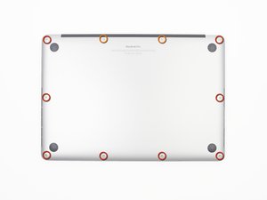
- Remove the following P5 pentalobe screws securing the lower case to the MacBook Pro:
- Eight 3.0 mm
- Two 2.3 mm
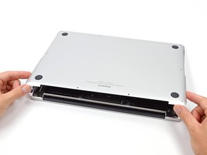
- Lifting from the edge nearest the clutch cover, lift the lower case off the MacBook Pro.
- Set the lower case aside.
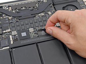
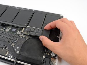
- Peel back the warning label covering the battery connector.

- Using the flat end of a spudger, gently pry the battery connector straight up out of its socket on the logic board.
- Bend the battery cables back and out of the way, ensuring that the battery connector doesn't accidentally make contact with the logic board.

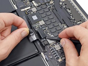
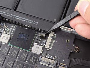
- Use a spudger or tweezers to pry the three AirPort antenna cables straight up off of their sockets on the AirPort board.

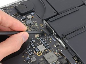
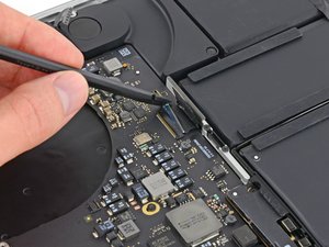
- Use the tip of a spudger to push the camera cable's plug toward the fan and out of its socket on the logic board.


- Insert the flat end of a spudger underneath the rubber heat sink cover on the right fan.
- Slide the spudger underneath the length of the cover, releasing the adhesive.
- Lift the cover and flip it back so that you can access the cables underneath.


- Use your fingers to pull the AirPort/Camera cables up off the fan.
- Carefully de-route the cables from the plastic cable guide.


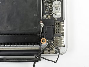
- Use the flat end of a spudger to pry the rubber hinge covers up off the left and right hinges.


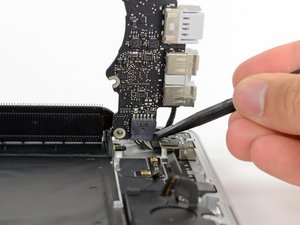
- Using the flat end of a spudger, pry the I/O Board connector straight up out of its socket on the logic board.
- In a similar fashion, remove the I/O Board cable connector from its socket on the I/O Board.
- Remove the I/O Board cable from the MacBook Pro.

- Remove the single 2.9 mm T5 Torx screw securing the AirPort card to the logic board.


- Grasp the sides of the AirPort card and lift it up to a shallow angle (5-10˚) to separate the light adhesive adhering it to the logic board.
- Pull the AirPort card parallel out of its connector on the logic board to remove it.


- Use the tip of a spudger to flip up the retaining flap on the right fan ribbon cable ZIF socket.
- Starting at the top of the cable, slide a plastic opening tool under the right fan cable to free it from the logic board.

- Remove the following three screws securing the right fan to the logic board:
- One 4.4 mm T5 Torx screw
- One 3.9 mm T5 Wide Head Torx screw
- One 5.0 mm T5 Torx screw with 2 mm collar

- Lift and remove the right fan out from the MacBook Pro.

- Use the flat end of a spudger to lift the rubber heat sink cover up off the left fan.

- Remove the following three screws securing the left fan to the logic board:
- One 4.4 mm T5 Torx screw with 2 mm collar
- One 5.0 mm T5 Torx screw with 2 mm collar
- One 3.9 mm T5 Wide Head Torx screw


- Use the tip of a spudger to flip up the retaining flap on the left fan ribbon cable ZIF socket.
- Starting at the top of the cable, slide a plastic opening tool under the left fan cable to free it from the logic board.
- Lift the left fan out of the device.

- Remove the single 3.1 mm T5 Torx screw securing the SSD to the logic board.

- Slightly lift the rightmost side of the SSD and firmly slide it straight away out of its socket on the logic board.


- Use the tip of a spudger to flip up the I/O board data cable lock and rotate it toward the battery side of the computer.
- Use the flat end of a spudger to slide the I/O board data cable straight out of its socket on the logic board.


- Remove the two 3.1 mm T5 Torx screws securing the I/O board to the logic board.
- On some models, also removing the silver 3.5 mm T5 Torx screw from the heatsink can aid in I/O board removal.
- Carefully lift the I/O board and remove it from the lower case.

- Use the flat end of a spudger to pry the left speaker connector up and out of its socket on the logic board.
- Use the tip of a spudger to pry the right speaker connector up and out of its socket on the logic board

- Peel back the tape covering the top of the keyboard ribbon cable connector.
- Use the flat end of a spudger to flip up the retaining flap on the keyboard ribbon cable ZIF socket.
- Use the flat end of a spudger to push the keyboard ribbon cable out of its socket.

- Use the flat end of a spudger to pry the trackpad ribbon cable connector up out of its socket.

- Use the flat end of a spudger to pry the keyboard backlight connector up from its socket on the logic board.

- Use the tip of a spudger or your fingernail to flip up the retaining flap on the microphone ribbon cable ZIF socket.
- Pull the microphone ribbon cable out of its socket.


- Use the tip of a spudger to flip up the display data cable lock and rotate it toward the DC-In side of the computer.
- Pull the display data cable straight out of its socket on the logic board.

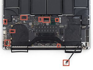
- Use the flat end of a spudger to carefully pry off the rubber screw cap on the raised screw head near the MagSafe 2 connector.

- Remove the following six screws securing the logic board to to the upper case:
- One 3.1 mm T5 Torx screw
- One 2.5 mm T5 Torx screw
- One 5.5 mm silver, raised-head T5 Torx screw
- Two 5.7 mm T5 Torx screws
- One 3.8 mm silver T5 Torx screw

- Lifting from the side nearest the battery, rotate the logic board toward the top of the MacBook Pro.
- Using the flat end of a spudger, carefully push the MagSafe 2 connector out of its socket on the bottom of the logic board.

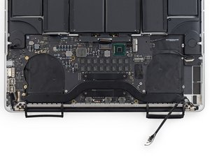
- Remove the logic board assembly from the MacBook Pro.
- Second photo, clockwise from top: battery, right speaker, keyboard backlight, AirPort/camera, display, microphone, left speaker, keyboard, and trackpad.


- Remove the two 2.5 mm T5 Torx screws securing the MagSafe DC-In board to the upper case.
- Slide the MagSafe DC-In board towards the right to free it from its recess within the upper case.
- Lift and remove the MagSafe DC-In board out of the upper case assembly.
To reassemble your device, follow these instructions in reverse order.