By Brett Hartt • Difficulty: Difficult
Use this guide to potentially repair PlayStation 3s with the "Yellow Light of Death" error.
This procedure may not completely revive your console. Since the “Yellow Light of Death” is a generic hardware error, the issue can range from an overheating CELL/RSX from dried thermal paste underneath the IHS, bad NEC/TOKIN capacitors, a short on the board, faulty RSX, etc. This guide may only temporarily fix consoles with a faulty flip chip (most likely RSX but CELL could also be at fault). An RSX/CELL replacement (requiring a BGA rework station) would be required to permanently repair a console with a faulty flip chip.
Note: Your PlayStation may look slightly different inside. Be cautious when performing this process on your machine.
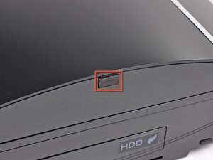

- Use the tip of a spudger to remove the black rubber screw cover from the side of the PS3.

- Remove the single 8.5 mm T10 Security Torx screw from the smart plate.


- Pull the smart plate toward the hard drive bay, then lift it off the body of the PS3.
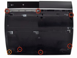
- Remove the following seven screws:
- Six 52 mm Phillips screws
- One 30 mm Phillips screw

- Lift the top cover from its rear edge and rotate it toward the front of the PS3.
- Remove the top cover.
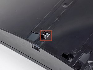
- There is a plastic hook located in a hole on the top back right hand side corner. Carefully push the plastic hook a bit from the rear of the machine with a spudger to release the rear right of the casing.

- Disconnect the Blu-ray power cable from the motherboard.

- Lift the Blu-ray drive from the edge nearest the power supply and rotate it away from the chassis enough to access its ribbon cable.


- Use your fingernail to flip up the retaining flap on the Blu-ray ribbon cable socket.
- Pull the ribbon cable out of its socket.
- Remove the Blu-ray drive from the PS3.

- Pull the control board ribbon cable straight up and out of its socket on the motherboard.


- Remove the two 12 mm Phillips screws securing the control board to the lower case.
- Remove the control board and its attached cable from the PS3.

- Remove the following eight screws securing the motherboard assembly to the lower case:
- Seven 12 mm Phillips screws (ph2)
- One 30 mm Phillips screw

- Remove the control board bracket.


- Use the flat end of a spudger to pry the hard drive bay cover away from the lower case.
- Remove the hard drive bay cover.

- Lift the motherboard assembly out of the lower case.

- Remove the 7.7 mm Phillips screw securing the ground strap to the chassis.


- Pull the AC-In cables slightly away from the rear cover for clearance to access the AC-In connector.
- While depressing its locking mechanism, pull the AC-In connector out of its socket on the power supply.

- Pull the AC inlet out from the bottom of the rear cover, minding any of its cables that may get caught.


- While lightly pulling the rear cover away from the logic board assembly, use the flat end of a spudger to release the clips along the top and bottom edges of the rear cover.

- Remove the rear cover from the logic board assembly.


- De-route the fan cables from the plastic finger molded into the heat sink.
- Disconnect the fan from the motherboard.

- Remove the two 9 mm Phillips screws securing the memory card reader to the chassis.


- Lift the memory card reader out of the PS3 enough to access its ribbon cable.
- Flip up the retaining flap on the memory card reader ribbon cable socket.
- Pull the ribbon cable out of its socket and remove the memory card reader.

- Disconnect the DC-In cables from the front of the heat sink.

- Remove the five 9 mm Phillips screws securing the power supply to the chassis.

- Lift the power supply by its front edge to clear the two posts attached to the motherboard.
- Remove the power supply.

- Remove the four 16.5 mm shouldered Phillips screws securing the heat sink to the motherboard.
- Remove the two brackets held under the screws you just removed.

- Lift the motherboard assembly off the heat sink.
- Be sure to apply a new layer of thermal paste when reattaching the heat sink.


- Flip up the retaining flap on the Blu-ray ribbon cable socket.
- Remove the Blu-ray ribbon cable.


- Flip up the flap on the memory card reader ribbon cable socket and remove the ribbon cable.


- Flip up the retaining flap on the Wi-Fi/Bluetooth ribbon cable socket.
- Pull the Wi-Fi/Bluetooth ribbon cable out of its socket.

- Disconnect the DC-In cable from the motherboard and set it aside.

- Disconnect the PRAM battery from the motherboard.


- Rotate the PRAM battery slightly counter-clockwise and remove it from the motherboard assembly.

- Remove the blue 8 mm Phillips screw securing the hard drive cage to the chassis.


- Push the hard drive cage toward the front of the motherboard assembly.
- Remove the hard drive from the motherboard assembly.

- Remove the two 3.7 mm #0 Phillips screws securing the chassis to the hard drive socket.

- Remove the two 8.3 mm #0 Phillips screws securing the two halves of the motherboard together.

- Carefully feed the Wi-Fi/Bluetooth ribbon cable through the hole in the top motherboard cover.
- Remove the top motherboard cover.

- Remove the motherboard from the bottom motherboard cover.


- Flip up the retaining flap on the Wi-Fi/Bluetooth ribbon cable socket.
- Remove the Wi-Fi/Bluetooth ribbon cable from the motherboard.
- Motherboard remains.


- Using the flat end of the spudger, remove the old thermal paste off the CPU and GPU on the motherboard.
- Using a cleaner such as Arctic Silver's ArctiClean or high alcohol content rubbing alcohol, clean the CPU and GPU.


- Using your fingers or the flat end of a spudger, remove the old thermal pads on the logic board as indicated:
- Large square thermal pads
- Small square thermal pads
- Small rectangular thermal pads (located on the underside of the board, as highlighted in the second picture)

- Set the heat gun to "Low" or around 300C (575F), and let it run for a few seconds to reach operating temperature.
- Holding the motherboard upright, warm up the entire board with the heat gun. The board should be warm, but not too hot.


- Set the motherboard on a support so that the CPU and GPU are completely supported and level.


- Using a circular motion, evenly heat (using low heat) the two processors labeled "RSX" and "CELL" for 2 minutes while keeping the gun about 1/2" above the chip. For the Lower two areas heat for 30 seconds following the same distance guidelines from above.
- Begin heating the GPU, marked "RSX", and heat the chips in a zig-zag order.


- Continue heating the chips using the same circular motion as described above, for about 25 seconds each.


- If you have not applied thermal paste before you can check our thermal paste guide whilst it is cooling.
- Apply a thin bead of thermal paste on the CPU.
- Using the thermal paste spreader card, spread the paste out thinly and evenly on the chip.
- In the same way, apply a thin layer of thermal paste on the GPU.
- Clean up any excess thermal paste off the motherboard.


- Apply the fresh thermal pads to the motherboard in the locations indicated:
- Large square pads
- Small square pads
- Small Rectangular Pads
- Two 3cm x 3cm Squares
- Ten 1cm x 1cm Squares
- Five 1.5cm x 0.5cm rectangles

- Peel the remaining white plastic cover off the other side of thermal pads.
To reassemble your device, follow these instructions in reverse order starting at step 41.